Introduction & Theory
Centrifugal Pumps
The centrifugal pump utilizes a rotating impeller to impart rotodynamic force onto a fluid. A typical design for a centrifugal pump involves an axially rotating impeller housed inside a radially spiraling volute casing. The fluid enters the pump through the inlet, which is located along the rotating axis of the impeller. The fluid exits the pump through the outlet, which directs the fluid radially outward from the pump.
Like other pumps, the centrifugal pump operates by transferring power from a motor to the kinetic and potential energy of the fluid. The kinetic energy is used to radially accelerate the fluid outward from the pump casing. The volute casing ensures that the fluid itself undergoes a smooth energy transfer to increase the potential energy of the fluid. The potential energy propels the fluid through the outlet. Therefore, the two most important performance parameters of a centrifugal pump are the output pressure and output volumetric flow.
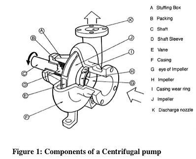
There are many advantages of the centrifugal pump design. The design is simple, and has the rotor as the sole moving part. The pump is able to operate at high speed, and can be coupled directly to an electric motor. It can handle high proportions of suspended solids. Several disadvantages also exist, however. The centrifugal pump has a relatively poor suction power, and needs priming. Uneven pressure distribution on the impeller causes cavitation on the blades. Also, it cannot efficiently pump very viscous fluids. There are six components that are considered in most centrifugal pumps: shaft, impeller, wear rings, volute casing, packing (mechanical seals), and bearings. Figure 1 depicts the various components of a centrifugal pump:

Multiple Disk Centrifugal Pump
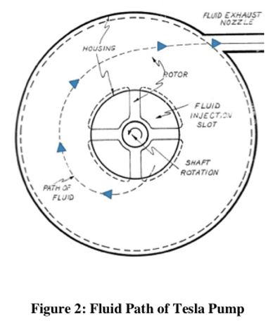
The multiple-disk centrifugal pump was patented by Nikolai Tesla, and is similar in design as a centrifugal pump. Instead of the impellers, multiple circular disks are keyed to a shaft, with a gap between each disk. A spiral flow of fluid between each disk will result an exchange in momentum between fluid and disks. The outward flows from the rotor go into a volute scroll or diffuser before leading to the outlet. As in a centrifugal pump, power is supplied by a motor attached to the pump.
There are many advantages of the multiple-disk centrifugal pump. It can be used with highly viscous fluids, fluids with abrasive particles, two-phase fluids, and other forms that conventional turbomachinery cannot adequately handle. A competently designed multiple-disk centrifugal pump is expected to have a more stable flow and lower cavitation occurrence than a regular centrifugal pump. Figure 2 depicts the fluid flow path between a pair of disks in a Tesla pump:

Pump Performance
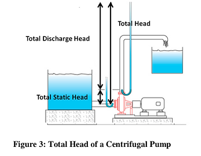
There are two performance parameters for a pump: the volumetric flow rate and outlet pressure head. Additionally, efficiency can be calculated by dividing power output by power supplied to drive the pump. Head expresses pressure as a unit of distance by converting to the equivalent height of water. The total head of a pump is comprised of the total static head plus the total dynamic head. The total static head is the height difference from water source to the centerline of the output nozzle. The total discharge head is the pressure output from the pump. Figure 3 depicts the three definitions of head found in a centrifugal pump:

A system curve of a pump is needed in the pump selection process. A system curve graphically represents the energy transfer equation for a given pump design condition. Each curve starts from the static head, and depicts the increase in head with the flow rate. The equation for a system curve is as follows:
where is a constant that describes the total system characteristics. The system curve is generated by operating the pump and obtaining the head value for a given flow rate. Figure 4 depicts a sample system curve of a centrifugal pump:

A pump performance curve describes the relation between flow rate and head. By either varying impeller diameters at a constant speed or varying speeds with a constant impeller diameter, several curves can be generated. Figure 5 depicts a sample pump curve, with varying RPMs:

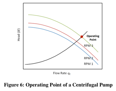
By superimposing the system curve with a pump curve, the operating point of a pump can be selected for a given parameter, such as RPM. Figure 6 depicts the operating point of a pump given its system and pump curves:

For a centrifugal pump, three affinity laws that relate speed or impeller diameter to the resulting performance, given the same efficiency:
a. Flow changes proportionally to speed
b. Pressure head changes by square to speed
c. Power changes by cube to speed
Based on these parameters we hope to be able to develop and qualify a Tesla pump in a similar manner.
References:
Journals
[1] Tadmor, Z. Mehta, P.S., Valsamis, L.N. and Yang, J., 1985, “Corotating Disk Pumps for Viscous Liquids” Ind. Eng. Chem. Process Des. Dev. 24(2), 311-320
[2] Crawford, M.E., and W. Rice., 1974, "Calculated Design Data for the Multiple-Disk Pump Using Incompressible Fluid," Journal of Engineering for Power, 96(3). pp. 274- 282.
[3] Hoya, G. P., and A. Guha., 2009, "The Design of a Test Rig and Study of the Performance and Efficiency of a Tesla Disc Turbine." Proceedings of the Institution of Mechanical Engineers, Part AL Journal of Power and Energy 223 pp. 451-65
[4] Engin, T., Ozdemir, M. and Cesmeci, S. “Design, testing and two-dimensional flow modeling of a multiple-disk fan” Experimental Thermal and Fluid Science, 33 pp.1180- 1187
[5] Jacobson, R. “The Tesla Bladeless Pumps and Turbines.” 26th IECEC 4 pp 445-450
Dissertations
[1] Leaman, A.B., 1950, “The Design, Construction and Investigation of a Tesla Turbine”. Masters Thesis, University of Maryland.
[2]Crawford, M.E. ,1972, “A Composite Solution Method for Analytical Design and Optimization Studies of a Multiple-Disk Pump”. Ph.D. Dissertation, University of Arizona, Tempe.
[3] Harwood, P., 2008, “Further Investigations into Tesla Turbomachinery,” University of Newcastle.
Patents
[1] Tesla, N. “Tesla Turbine.” U.S. Patent 1,061,206. 6 May 1913.
[2] Tesla, N. “Fluid Propulsion.” U.S. Patent 1,061,142. 6 May 1913.
[3] Possell, C.R. “Bladeless Pump and Method of Using Same” U.S. Patent 4,403,911. 13 Sep 1983.
[4] Possell, C.R. “Method for Pumping Slurry and Apparatus for Use Therewith” U.S. Patent 4,347,032. 31 Aug 1982.
Internet
[1] Drury, Robert., 2009, "Bladeless Turbine." From http://home.earthlink.net/~rtdrury/stc.turbine.html.
[2] Opensource Ecology. “Tesla Turbine.” From http://opensourceecology.org/wiki/Tesla_Turbine.
[4] Redmond, Steve., 2003, “Building a Disk Turbine.” from http://www.sredmond.com/disk_turbine.htm
[5] Swithenbank, Alan., 2008, "Boundary Layer (Tesla) Turbine Page." from http://www.stanford.edu/~hydrobay/lookat/tt.html
[6] Troy, Steven., 2010, “Building a Tesla Turbine from Hard Drive Platters.” from http://www.phys.washington.edu/users/sbtroy/Tesla_Turbine/Tesla_Turbine.html
